PCB2G
Overview
PCB2G software can be used to convert bitmap images of
PCB
into CNC G-code for
LINUXCNC. G-code can be used to route
dividing lines into copper layer of PCB.
Scanned images from paper or converted postscript or pdf files converted
to bitmap images can be used as input image. Another way to get input
images is generating bitmap images from electrical CAD software like KICAD or EAGLE and others.
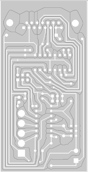
Input image is analyzed by PCB2G. PCB2G searches for holes positions and
calculates dividing lines. Vectorized dividing lines and drill positions can
be found in output CNC g-code.
Input files
Example input image
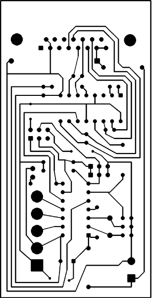 is analyzed for dividing lines
Input file must be in portable bitmap or portable graymap format. More
information can be found in
NETPBM library. You can use
convert from
imagemagick package co convert other image formats into portable bitmap format.
An example input files (508DPI or X=44.45 Y=87.63) can be downloaded here and
here.
An optional drill input file can be used to define precise positions of holes
on board. Only KICAD output file was tested. More informations can be found
in this HOWTO and example drill file for PCB can
be downloaded here.
Other example input file (186DPI) without drill file can be downloaded here.
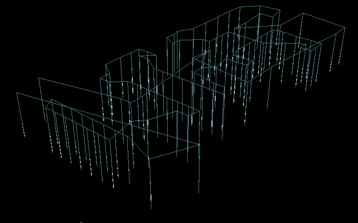
Output files
Final G code can be used to route dividing
lines and mark drill positions.
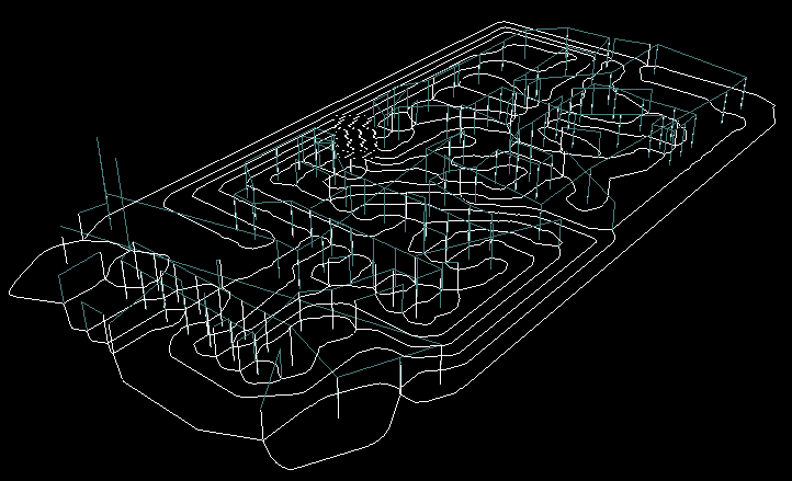
The same code with turned
Block Delete switch can be used for drilling PCB holes.
Source code under the GPL is available
here
Alternative CAM generators for CNC code from PCB:
pcb-gcode,
pcb2gcode and
cad-py
Author: popovecATfei.tuke.sk
Last update: Jan 26, 2016